All,
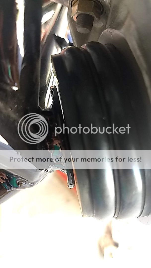
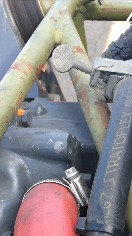
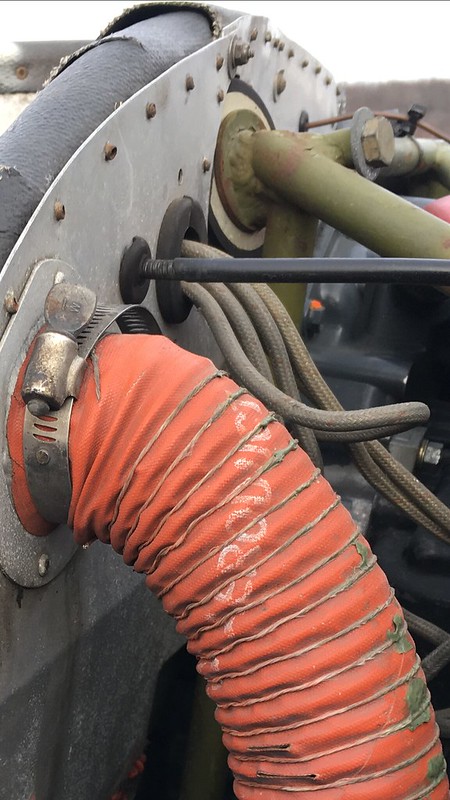
I am helping my mechanic install my overhauled engine. We are installing the vibration isolators. There is a gap between the engine mount welded on washer and the vibration isolators. Is this a normal thing on maules or do I have something wrong? BTW it is a1981 M6-235.
Engine mount gap
-
kneel
- Posts: 36
- Joined: Wed Feb 03, 2010 6:20 am
- Location: Wray, CO
- Contact:
-
gdflys

- 100+ Posts
- Posts: 283
- Joined: Wed Jul 24, 2013 11:31 pm
- Location: CT
- Contact:

-
riverbuggy

- 100+ Posts
- Posts: 172
- Joined: Tue Dec 21, 2010 5:26 pm
- Location: Sidney, Maine
- Contact:
-
gdflys
- 100+ Posts
- Posts: 283
- Joined: Wed Jul 24, 2013 11:31 pm
- Location: CT
- Contact:
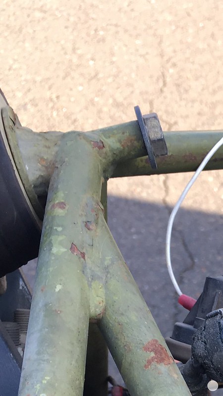
They definitely look bent either by previous damage or during the welding process. I went back and looked at my pictures during my overhaul process and my mount flanges are all flat with no space.
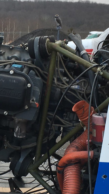
Closest pics I have before the mount was redone.
 Engine mount flanges by gdflys1gregflys, on Flickr
 Engine mount flanges by gdflys1gregflys, on Flickr
 Engine mount flanges by gdflys1gregflys, on Flickr
 Engine mount flanges by gdflys1gregflys, on Flickr
 Engine mount flanges by gdflys1gregflys, on Flickr
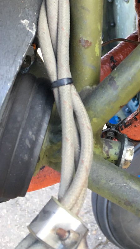
Closest pics I have before the mount was redone.
Engine mount flanges by gdflys1gregflys, on FlickrEngine mount flanges by gdflys1gregflys, on FlickrEngine mount flanges by gdflys1gregflys, on FlickrEngine mount flanges by gdflys1gregflys, on FlickrEngine mount flanges by gdflys1gregflys, on FlickrGreg Delp
1979 M-5-235C
CT
ATP, CFI, A&P/IA
1979 M-5-235C
CT
ATP, CFI, A&P/IA
-
freedom

- 100+ Posts
- Posts: 239
- Joined: Fri Jul 17, 2015 6:34 am
- Contact:
-
riverbuggy
- 100+ Posts
- Posts: 172
- Joined: Tue Dec 21, 2010 5:26 pm
- Location: Sidney, Maine
- Contact:
-
gdflys
- 100+ Posts
- Posts: 283
- Joined: Wed Jul 24, 2013 11:31 pm
- Location: CT
- Contact:
-
riverbuggy
- 100+ Posts
- Posts: 172
- Joined: Tue Dec 21, 2010 5:26 pm
- Location: Sidney, Maine
- Contact:
-
kneel
- Posts: 36
- Joined: Wed Feb 03, 2010 6:20 am
- Location: Wray, CO
- Contact:
Engine mount gap
All,
Thanks for the help. After talking with my mechanic some more we decided to fix it like Riverbuggy mentioned. It was involved in an incident. It was a low speed, low power, taxi incident. It should not have caused this damage. Everything in the engine was checked and was fine. Freedom, I did blast it in a cabinet with glass bead.
-Kneel
Who is online
Users browsing this forum: No registered users and 18 guests